


PCB Manufacturing Services
Rigid-Flex PCB Prototype Fabrication Service
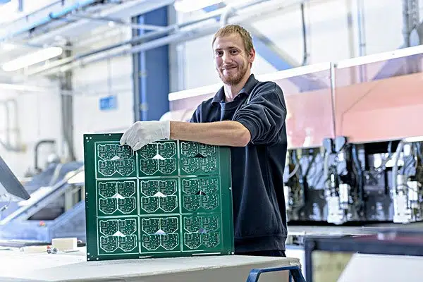
Rigid-Flex PCB Board
JHYPCB Rigid-flex PCB board manufacturing solutions are customized for several top electronic industries. Fabricated with dependable high standard internal control and reliability, our Rigid-flex PCB board is built to face up to the pains of aerospace, Robot control, medical, and military applications. As a reliable replacement for wire and wire harness assemblies, rigid flex circuits provide a major cost saving with no reduction in performance. Our PCB engineer team can assist you from the early rigid-flex design stages of your application all thanks to final production for all of your flex and rigid-flex circuit needs.
Rigid-flex Printed Circuit Board
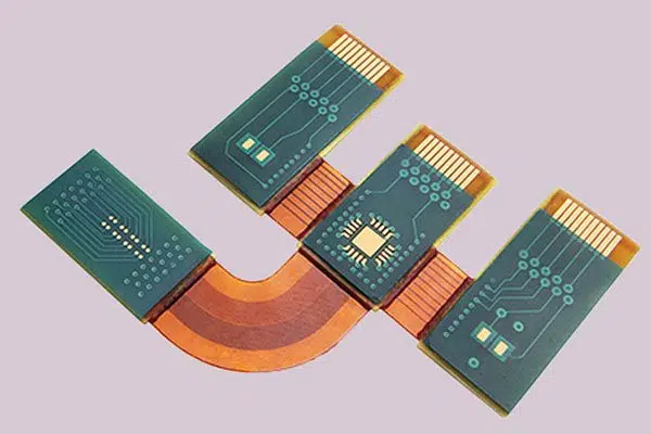
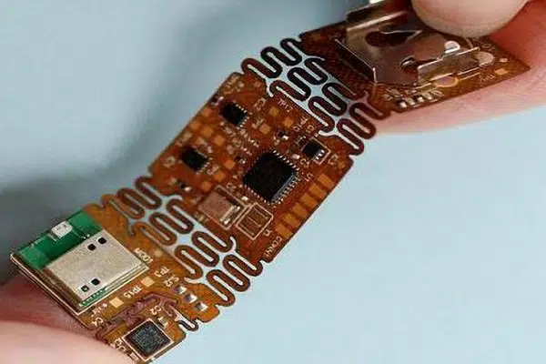
What is Rigid Flex PCB?
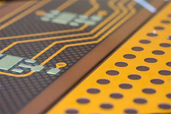
Rigid-Flex printed circuit boards are boards employing a combination of flexible and rigid board technologies in an application. Most rigid-flex boards carry their multiple layers of flexible circuit substrates attached to at least one or more rigid boards externally and/or internally, depending upon the planning of the appliance. The flexible substrates are designed to be in a very constant state of flex and are usually formed into the flexed curve during manufacturing or installation. Rigid-flex printed circuits are used in the military and aerospace industries for over 20 years. In most rigid-flex PCB boards, the circuitry consists of multiple flexible circuit inner layers selectively attached together using an epoxy pre-preg bonding film, just like a multilayer flexible circuit. However, a multilayer rigid flex PCB fabrication incorporates a board externally, internally, or both as required to accomplish the planning.
Rigid flex designs are more difficult than the look of a typical rigid board environment, as these boards are designed in a 3D space, which also offers greater spatial efficiency. By having the ability to style in three dimensions, designers can twist, fold and roll the flexible board substrates to realize their desired shape for the ultimate application’s package. Rigid flex circuits combine the most effective rigid boards and versatile circuits integrated into one circuit. Designs are rigid where extra support is required and versatile around corners and areas requiring extra space.
Types of Rigid Flex PCB
There are some types of Rigid-Flex PCB. Let’s see them:
1. Single Layer Rigid Flex PCB
For the one-sided type, they need only one conductive material layer. The board’s other side allows for the mixing of various electronic components on your board. Furthermore, they’re fabricated from one layer of rigid-flex substrates combined together. In contrast to the opposite rigid flex types, you’ll easily manufacture and style them.
Learn more about single-sided PCB Board.
2. Double Layer Rigid Flex PCB
For rigid-flex boards, they’re composed of one rigid substrate layer, while the opposite layer may be a flexible substrate. This rigid layer aids in the enhancement of compactness. The flex substrate on the opposite hand plays an enormous role in flexibility. Furthermore, double-sided rigid PCBs with flex permit more routing traces. The vias make this possible, which alternates between both layers. Most PCB engineers prefer this kind of rigid-flex PCB thanks to the flexibility and their capability to cut back the board size.
Learn more about what double sided PCB is?
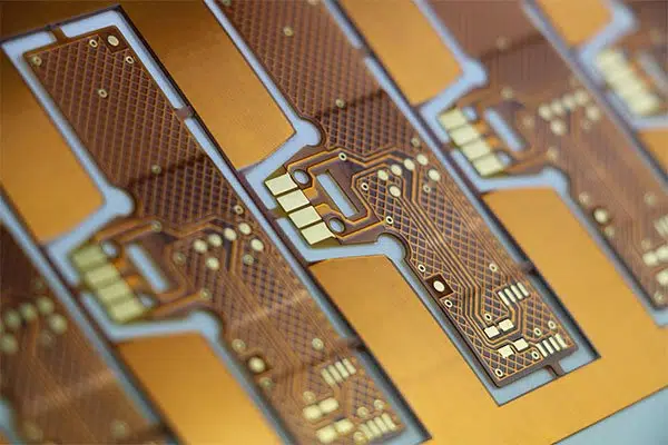
3. Multilayer Rigid Flex PCB Board
This is a rigid flex that features a minimum of three conductive layers of any of both substrates. These substrates function as insulators.
Benefits of Rigid Flex PCB
- Space requirements are minimized by applying 3D
- The board size and overall system weight may be reduced by removing the requirement for connectors and cables between the individual rigid parts.
- By maximizing space, there’s often a lower count in parts.
- Fewer solder joints assure higher connection reliability.
- Handling during assembly is simpler as compared with flexible boards.
- Simplified PCB assembly processes.
- Integrated ZIF contacts provide simple modular interfaces to the system environment.
- Test conditions are simplified an entire test before installation becomes possible.
- Logistical and assembly costs are significantly reduced with Rigid-Flex boards.
- It’s possible to extend the complexity of mechanical designs, which also improves the degree of freedom for optimized housing solutions.
Rigid-Flex PCBs Fabrication Applications
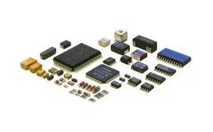
Rigid-Flex PCBs offer a large array of applications, starting from smart devices to cell phones and digital cameras. Increasingly, rigid-flex board fabrication has been employed in medical devices like pacemakers for their space and weight reduction capabilities. The identical advantages for rigid-flex PCB usage will be applied to smart control systems.
In consumer products, rigid-flex doesn’t just maximize space and weight but greatly improves reliability, eliminating many needs for solder joints and delicate, fragile wiring that are susceptible to connection issues. These are just a few examples, but Rigid-Flex PCBs are often wont to benefit nearly all advanced electrical applications, including testing equipment, tools, and automobiles.
Rigid-Flex PCBs Manufacturing Process
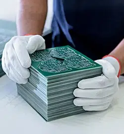
The rigid-flex PCB manufacturing process is time-consuming and laborious when put next to traditional rigid board fabrication. It involves several steps that have got to be allotted with extreme accuracy. Mishandling or misplacing any of the flexible components within the board affects the efficiency and sturdiness of the ultimate assembly substantially.
Rigid-flex circuit card manufacturers assemble the boards by following the steps listed below.
Step 1. Preparing the bottom Material
The primary step involved in the board fabrication is preparing/cleaning the laminate. The laminate, which contains a copper layer with adhesive or adhesives coating must be cleaned thoroughly before processing with other fabrication processes. This pre-cleaning is vital because copper coils are normally offered by vendors with anti-tarnish features to produce oxidation protection. However, this coating poses a hindrance to rigid-flex PCB manufacturing, hence must be removed.
To remove the coating, PCB manufacturers commonly perform the subsequent steps.
- First, the copper coil is totally immersed in an acid solution or exposed to an acid spray.
- The copper coil is then micro-etched by treating with sodium persulphate.
- Finally, the coil is coated comprehensively using appropriate styles of oxidation agents to forestall adhesion and oxidation.
Step 2. Circuit Pattern Generation
Generating circuit patterns is the next step followed by laminate preparation. Nowadays, this circuit pattern exposure is finished using two main techniques, such as:
- Screen Printing – This system is popular because it can generate the desired circuit patterns/deposits directly onto the surface of the laminate. the full thickness isn’t over 4–50 microns.
- Photo Imaging – Photo imaging is the oldest but still the foremost popularly used technique for depicting the circuit traces on the laminate. During this method, a dry photoresist film consisting of the specified circuitry is placed in close contact with the laminate. This assembly is then exposed to UV light, which helps transfer the pattern from the photomask to the laminate. The film is then chemically removed, yielding the laminate with the required circuit pattern.
Step 3. Etch the Circuit Pattern
Following the circuit pattern generation, next is etching the copper laminate containing the circuit pattern. Rigid-flex manufacturers either dip the laminate in an etch bath or it’s sprayed with an etchant solution. Either side of the lamination is etched simultaneously to realize the required results.
Step 4. Drilling Processes
Now, the time is for drilling the required number of holes, pads, and vias. High-speed drilling tools are wont to make precision holes. To make ultra-small holes, rigid-flex circuit board manufacturers use laser drilling techniques. Usually, Excimer YAG and CO2 lasers are wont to drill small and medium holes within the substrate.
Step 5. Through-hole Plating
This is often one of all the crucial steps in the rigid-flex PCB manufacturing process that has got to be administrated with extreme precision and care. After holes with required specifications are drilled in, they’re deposited with copper and chemically plated. This can be done to create layer-to-layer electrical interconnection.
Step 6. Apply Cover lay or Covercoat
It’s crucial to shield the highest and bottom sides of the flex circuit by applying a canopy lay. This is often done to produce comprehensive protection to the circuit from aggressive atmospheric conditions, harsh chemicals, and solvents. In most cases, manufacturers use a polyimide film with adhesive as a canopy lay material. Cover lay material is imprinted onto the surface using screen printing, which is then cured with UV exposure. So as to make sure proper adhesion of the duvet lay the material onto the substrate, cover lays are laminated under specified limits of warmth and pressure. Unlike the duvet lay material, which may be a laminated film, a covercoat is a material that’s literally applied onto the surface of the substrate. the choice regarding the sort of coating must be made after considering the manufacturing methods, materials used, and therefore the application areas. Both covers lay and covercoat augment the electrical integrity of the whole assembly.
Step 7. Ablation of the Flex
Blanking or cutting the individual flex board from the assembly panel is one more important step that has got to be executed with caution. When producing rigid-flex PCBs in high volume, manufacturers usually choose the hydraulic punching method. However, the identical isn’t chosen for prototyping or small production runs thanks to the high tooling cost involved. When creating prototype rigid-flex PCBs in small production runs, a specialized blanking knife is employed.
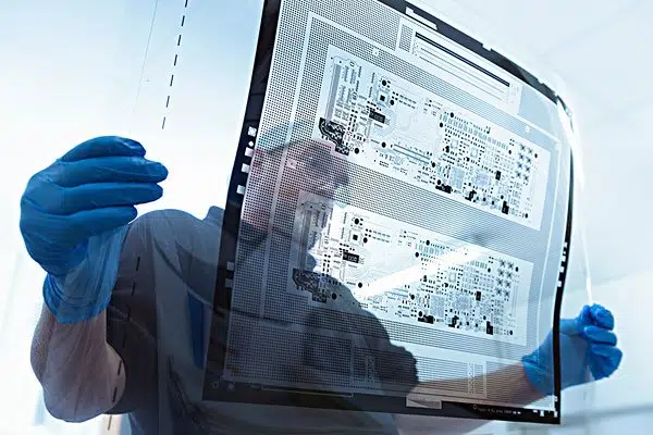
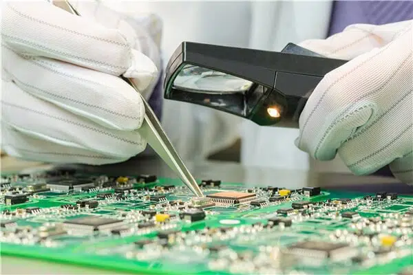
Step 8. Electrical Testing and Verification
The last and ending in rigid-flex circuit board manufacturing is testing and verification. The boards undergo stringent electrical testing for continuity, isolation, circuit performance, and quality against the look specifications. Several types of testing methods are used, including grid and flying probe test methods.
Rigid-flex PCBs are vastly replacing traditional rigid PCBs in several applications. Since the standard of the PCBs determines the integrity of the complete electrical assembly, it’s imperative that they need to be manufactured to maintain a high level of quality. Little design or manufacturing flaw drastically affects the performance, functionality, and sturdiness of the ultimate product. Hence, PCB manufacturers must be extremely careful right from the start of the design and designing to material selection, manufacturing, and testing. This helps in producing a board that’s superior in performance and unmatched in reliability.
Explore our PCB Manufacturing and assembly Service

Read More
- How much does PCB Fabrication Cost?
- PCB Fabrication and Assembly Services Manufacturer In China
- What are the Advantages of a Prototype PCB Assembly?
- Why Choose China PCB Assembly Manufacturer?
- What is PCB Panelization and its Methods in PCB Manufacturing?
- Outer Layer Processing of PCB Fabrication Process
- Inner Layer Processing of PCB Fabrication Process