


The bill of materials (BOM) is of preliminary significance within every device’s design and production phase, ranging from the printed circuit board (PCB). Without an in-depth and punctiliously compiled BOM, the project may require several unnecessary revisions, with potential issues and delays during production. While the BOM might not seem to be the foremost important aspect in PCB development, it’s undoubtedly one of the foremost critical.
What is BoM?
BOM – Bill of Materials is a listing of the raw materials, parts, and assemblies likewise because of the required quantity of every needed for a particular product manufacturing. In other words, it’s a listing of everything required, sort of a recipe required to create a product. It’s often noted as a production recipe, assembly component list, or product structure.
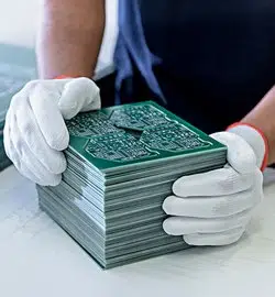
Take, for instance, a printed circuit Board – (PCB) manufacturer that must build 1,000 flexible circuits. A bill of materials for this sort of order will include all the parts that make the circuit, like components, equipment, cost, and more. Well-made BOM can contribute to the corporate by helping with estimating material costs, plan of the raw materials, internal control, and record maintenance. Bill of materials also reduces the waste and ensures the availability robustness.
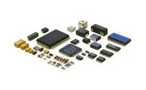
The bill of materials is nothing over an entire list of raw materials, electronic components, assembled and semi-assembled, small parts, and everything necessary for PCB manufacturing. A BOM must be accurate and detailed and not leave room for potential misunderstanding because it contains the knowledge used to manufacture the printed circuit board. It essentially contains the wants that the customer submits to the manufacturer.
How to fill a BOM?
Regardless of the actual tool used, the creation of a BOM is split into the subsequent typical steps:
- Design of the initial version of the document, pointing on top of the project name and the other useful information that permits immediate identification.
- Document organization identifies the users who can access it and their access rights (reading, writing, creation, cancellation, etc.). It’s also necessary to activate the change tracking system and founded the physical repository (with backup functionality) which will host the file.
- Column definition: each column of the spreadsheet must show on top the name that identifies the category, such as the name of the part, quantity, manufacturer, code, description and more.
- Rows filling: for every element belonging to the BOM, a row must be added and adequately filled. Since this data is necessary for the success of the task, the data entered must be accurate and in step with the Gerber files of the PCB.
- Keep the BOM updated: once started, the file must be kept to this point, tracking every revision produced.
Which information a BOM shall contain:
Although the knowledge contained within the BOM may differ from project to project, some basic information has got to always be present and related to each column of the table. A possible list is the following:
- Part number: Part Number is the code, also called MPN (Manufacturer Part Number), provided by the manufacturer to spot every single part. Since this number is a single and unique code used internationally, there’s no risk of confusion or misunderstanding between those that compile the list and people who use it.
- Manufacturer’s name: this field details the one part and allows people who use the BOM to directly access the manufacturer’s or distributor’s catalogue, identifying the part immediately and properly. For people who compile the BOM, this information is incredibly Critical. It’s necessary to verify, in advance, that every part is on the market and within the required quantity, ensuring that it is found at a value and in an exceedingly time compatible with the project budget. Otherwise, a replacement must be found, an operation that involves extra time and costs.
- Description: provides additional information on the part, like color, weight, measure, units of measure and electrical features (voltage, current, capacity or more), applicable to higher and uniquely detail the one item.
- Quantity: it specifies, for every part, the number of units required by the PCB design. It should be noted how, within the case of large-scale productions (exceeding some thousand divisions), discounts can commonly be received from the manufacturer.
- Reference: each part of the printed circuit board must have a novel reference (usually matching the PCB silkscreen) which allows spots where the part is going to be positioned on the printed circuit (for example, R1, R2, R3, etc. for resistors). The reference, generally written of a letter followed by a progressive number, also matches the data within the schematics.
- Mounting type: for several electronic components, a distinction must be made between surface mounting (SMD) or through hole (PTH).
- Package type: when applicable, the actual package utilized by the part shall be specified (e.g., QFN16 or 20-SSOP).
- The number of layers: with the proliferation of multilayer boards, it becomes important to specify which layer the part belongs to.
- Alternative part: if a part will be easily replaced without affecting the PCB design, it’s possible to point to another part to be used if the first one is no longer functional.
- BOM level: often, the bill of fabrics is arranged on several levels, each of which specifies a particular assembly or a sub-assembly. The amount indication allows us to simply navigate across the varied BOM levels. A multi-level BOM is additionally noted as hierarchical, while a single-level BOM is termed flat. A smartphone, as an example, consists of a SoC, display, memory, sensors, camera, wireless interface, connectors, screws and little parts, and more. Each of that sub-assembly could have an avid BOM. The camera BOM may further explode into its components, like lenses, processor, firmware, camera holder, etc.
- Phase: this field shows at which location of the project life cycle each detailed part is employed, for example: “in production”, “during development”, “not released”, “to be approved”, etc. This information is especially useful for highly innovative (NPI) projects because it allows us to simply track progress and build a sensible project schedule.