


PCB ASSEMBLY TESTING AND INSPECTION
In-Circuit Testing
What Is an In-circuit Test?
In-circuit testing (ICT) could be a combination of various testing instruments into one. The test system connects to the PCB via test probes which hook up with test points within the PCB. This electrically tests circuits and parts opposite censorious values. The foremost common defects which will be identified with ICT are solder shorts, missing components, component failures, lifted pins, component shifts, and poor soldering issues.
In-circuit testing (ICT) is the most robust style of PCB testing breathing. The high price reflects those tens of thousands of dollars, though the price will depend upon the board and fixture size, among other factors. An ICT, also referred to as a bed-of-nails test, powers up and actuates the individual circuitry on the board. The test is meant for 100% coverage in most cases, but you’ll catch up with 85-90% coverage. The great thing about ICT is that the 85-90% you get is completely freed from human error.
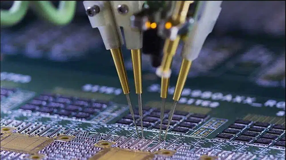
This test involves using fixed probes laid call in the simplest way that matches the look of the PCB. The probes examine the probity of the solder joint. The bed of nails tester pushes the board down on the bed of probes to begin the test. There are access points predesigned within the board that permits the ICT testing probes to form connections with the circuit. They put a specific amount of pressure on the connection to create sure it stays intact. ICT is commonly performed on more significant connections and ball grid arrays (BGAs). This test is for a “mature” product with only a few revisions expected. If you don’t have design-for-manufacturing as a part of your goal, with the right pads on the board, you’ll not be able to use an in-circuit test.
It is extremely important to conduct proper inspection and testing on the PCB to confirm that the performance of each component meets the very best standards and enables them to complete the testing within a brief span of your time. This particular technique has been used for several years and is very popular because it has the flexibility to provide responsive test requirements and every one of the main electronic firms uses this system to detect defects within the boards. ICT is fast, easy, and highly accurate in determining the fault within the circuits and is becoming hugely popular nowadays. you’ll be able to find a good sort of in-circuit test systems available within the market and every of those differs from one another in terms of its capabilities, testing procedures, and performance. Every PCB manufacturer should employ the proper tester so as to access the desired points on the circuitry.
It is easy to program while you’re detecting defects in circuit components and ensuring continuity and other related factors. It doesn’t cause operator error. It always takes around one or two minutes per assembly for testing the circuit and is very economical for bulk processing. Because it could be a comprehensive testing method, it’s highly reliable compared to the opposite testing methods. With this system, you’re assured of high fault coverage for handling manufacturing defects.
Methods
Special PCB Assembly Testing Steps uses in this Method:
In-circuit testing is a well-liked PCB testing way that a lot of printed circuit board manufacturers opt to use, and this method can find 98% of faults. The in-circuit testing method uses particular printed circuit board testing steps and equipment, including:
In-circuit Tester
The tester system contains a matrix of centuries or thousands of drivers and different sensors, these drivers and sensors perform the measurements for the test.
Fixture
A fixture attaches to the in-circuit tester and is the part that interchanges straightly with the board being tested. This fixture appears like a bed of nails and is intended specifically for the board in question. All “nail,” or sensor point, attaches to applicable points on the test board, feeding data back to the tester. Fixtures are generally the foremost expensive part of this technique.
Software
Software for the tester instructs the system on what tests to perform for every kind of board being tested and dictates the parameters for a pass or fail.
Using the ICT method, a manufacturer can test individual components and measure their performance, irrespective of the opposite components attached to them. Generally, this sort of testing is best for 3analog circuits since it’s best at measuring resistance, capacitance, and other analog measures. Additionally, the price of the equipment implies that this testing method is best suited to the ultimate testing of stable, high-volume products, not for low-volume productions or early testing stages where the look may change multiple times.
Advantages of In-Circuit Testing
With the peace of mind of straightforward, fast, rapid, accurate fault location, ICT is becoming more and more popular today. The testing method is vastly employed thanks to its several advantages including:
- In-circuit tester is extremely easy to program to detect defects in components, continuity than on.
- There is really little room for operator error.
- It will not take a protracted time to detect errors (usually 1-2 minutes per assembly).
- It is a highly reliable and comprehensive testing method as compared to other testing methods.
- In-circuit testing persuades high fault coverage for manufacturing faults.
- It is the most effective testing method for medium to high volume through-hole conventional assemblies.
- In-circuit test (ICT), which has been around for several years now, requires minimal maintenance costs.
Disadvantages of In-Circuit Testing
Every technology will have a group of drawbacks yet. In-Circuit testing is additionally not free from the identical. the subsequent is among the disadvantages related to ICT.
- Its test fixtures are expensive.
- ICT sometimes fails to spot connector faults in high density, small package size SMT components.
- It shows inconsistent results if test pins don’t make proper contact with the acceptable test pads.
- Its test pins have to be regularly cleaned and replaced to forestall failure.
- Although the testing method has some flaws, the technology remains considered the best thanks to testing a printed circuit board (PCB) assembly.
Quality is our lifeline. In order to ensure the quality of PCBA products, we will provide various PCB assembly tests and inspection methods according to customers’ requirements:
PCBA testing:
- In-Circuit Test (ICT)
- Functional Test (FCT)
- Burn-In Test
- Severe Conditions Test
- Fatigue Test
- Flying Probe Testing (FPT)
PCBA inspection:
- First Article Inspection (FAI)
- Manual Visual Inspection
- Automated Optical Inspection (AOI)
- X-Ray Inspection (AXI)
- Solder paste inspection (SPI)
During production and before delivery, we will also implement strict quality management:
- Incoming Quality Control (IQC)
- In-Process Quality Control (IPQC)
- Final Quality Control (FQC)
- Outgoing Quality Control (OQC)
Looking for a satisfactory PCB assembly manufacturer? Please ask for our help. For more information, please contact us at sales@pcbjhy.com.